Testing and Reorganizing Atom
At the end of adding memory instructions, Atom was looking a bit messy. I want to clean up the layout of Atom, and consolidate some of the circuitry to clean everything up. However, I am worried that I will break something as I do this, and right now I don’t have a great way to tell if I do. This page describes change between #memory-atom and #atom-refactor in the git repository.
How to Know if Something is Broken?
The solution to this problem is to write tests! With these, I will be able to validate that Atom still works like it did before. Digital has some testing tools, but they are for testing direct inputs and outputs of a circuit, and not the contents of RAM. They could be useful to add, especially for things like the ALU, jump decider, or control unit. I may add these later, but I want to start somewhere else. I am going to write a small series of programs that can be loaded into RAM, and each of which verify that some set of instructions work as expected.
Testing
First thing first, I need to know when a test is complete. I already added the HALT instruction, and the computer halting is a clear choice. A test is done when the computer halts. The first test that I will write is simply a single HALT instruction. If the computer halts, the test has passed.
After writing this test, I realized that I needed to record the expected value
of my tests, so I added a new TEST.md file that documents the purpose and
expected value of each test. In addition, it is in execution order. The tests
are going to build on each other, like using HALT to end the test, so I want to
know that certain instructions work so that I can use them in other tests.
Testing Set
Set is another very basic instruction that I will need to use in other tests. I
want to check a couple things: can I set low bits, can I set high bits, can I
set both? The test is simple, just execute set instructions on a few registers:
20ab 31cd 2257 3223 0fff.
This test found a bug introduced when adding the memory read/write instructions. They include a constant in the upper four bits of the immediate that were always forced to zero. When trying to load a value with a one in any of those bits, the compute crashes.
Testing Arithmetic
Testing arithmetic requires some values, which I can now set using either of the
set instruction: 2005 2102 1000 1220 1121 0fff.
Testing Comparisons and Jumps
Testing comparisons and jumps is a bit more tricky. There are many type of jump for different conditions, and I would like to avoid having to load up many different programs. Instead, I want to have one program that tells me which type of jump failed. I will use register zero to store the exit code. If it is zero when the computer halts, all test passed, otherwise its value indicates which test failed.
For each type of jump, I will jump over two instructions. One sets the value of
register zero, and the other is a halt. If the jump doesn’t happen, a value will
be set and the computer will immediately halt. A single test from the program is
shown below: 1283 1081 4402 2004 0fff.
This moves a predefined value into a register, performs addition, and executes a
jump. If the jump fails, 0x04 is written to register zero and the program
halts.
Testing Register Jump
I also need to test register jumps. I have decided not to test every jump type because the circuitry is the same between all jump types. I just want to focus on relative and absolute jumps. To that end, the program is very simple:
SETLO r1 0x02
RRJMP r1
SETLO r0 0x01
HALT

SETLO r1 0x07
RJMP r1
SETLO r0 0x02
HALT
Testing Memory Read and Write
Testing memory introduces an interesting new concept, and that is that data can
be encoded directly into memory when the program is loaded. For this test, I
include 0x0008 in memory at 0x0004. I read that, add it to itself, and write
it back into memory at the result (which isn’t necessary, but is neat).
Because the value is 0x0008, it is written back to 0x0010.
READ r0 0x4 r1
ADD r1 r1
WRITE r1 0x r1
HALT
0x0008
Refactoring
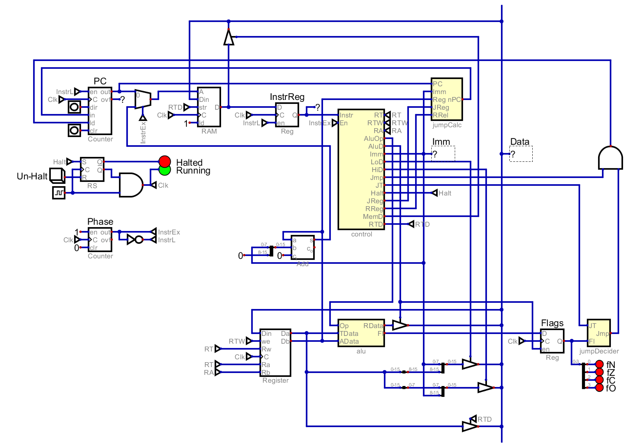
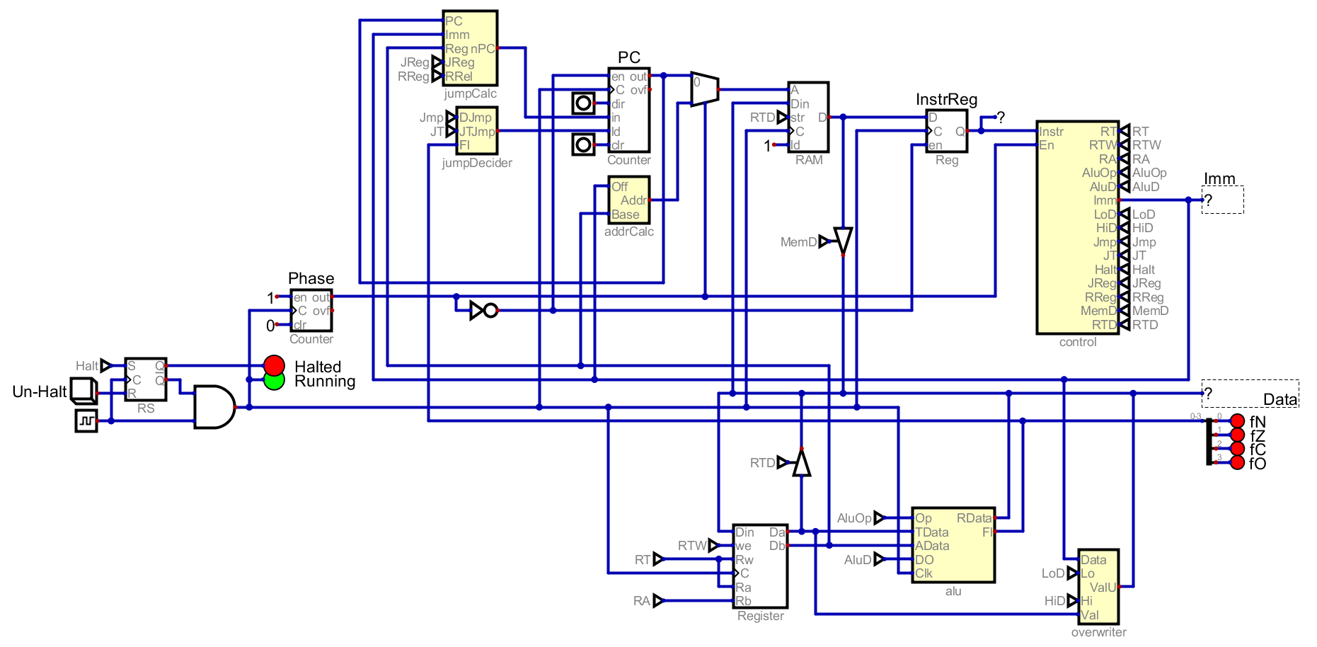
This small suite of tests covers all instructions. There are definitely still some holes in it, but I think this is sufficient for now. After solving the bug revealed by the set test, all test pass and the computer is working. As a reminder, it looks like this.
First, I want to centralize around a core bus, including more than just the data line. This way I can route various lines to many components without there being random wires all over the place.
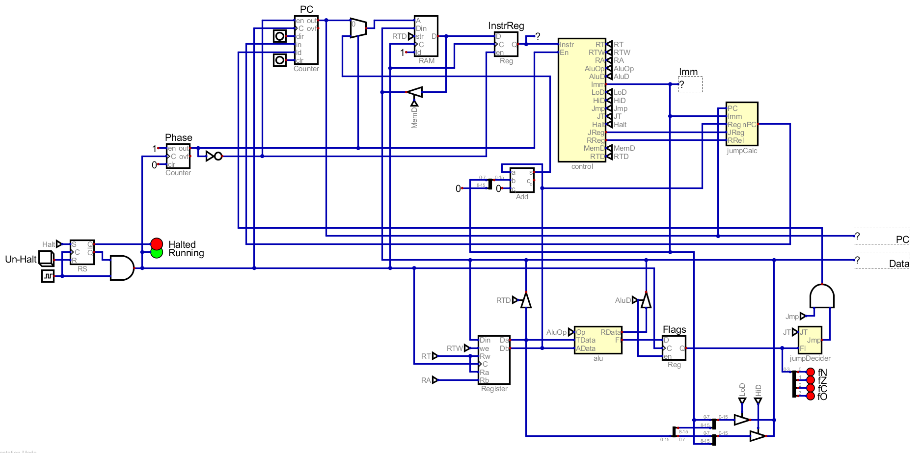
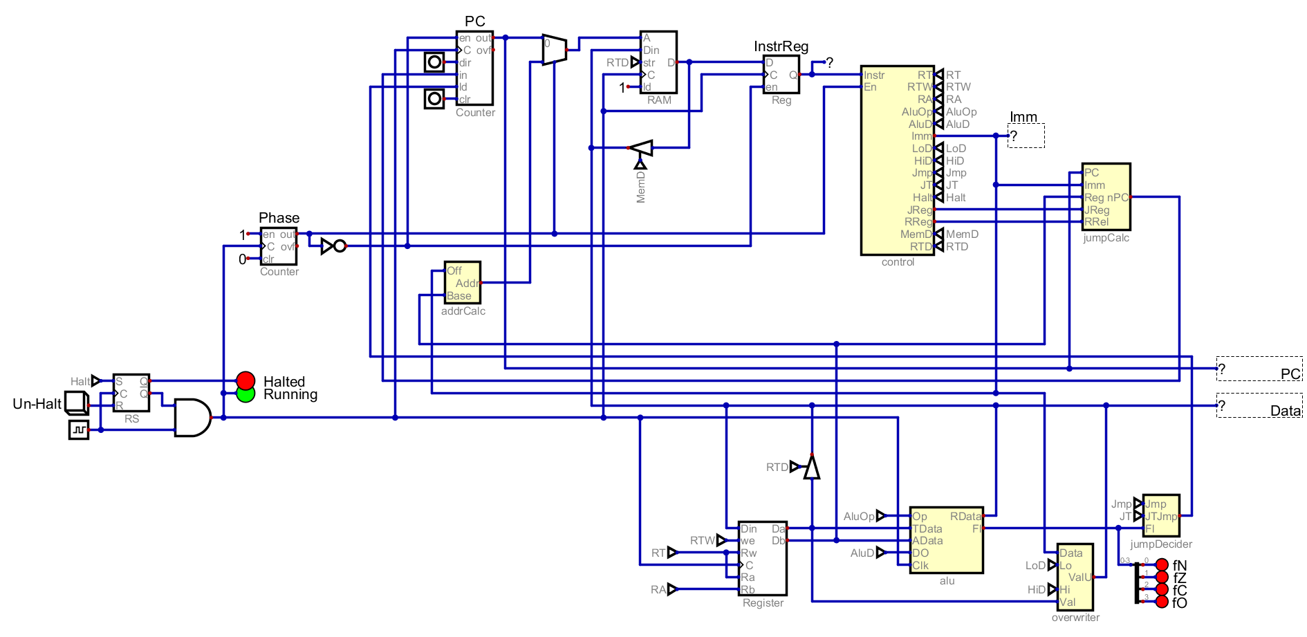
I also moved the control signal to tunnels, which removes a lot of wiring. I would like to being them back over time, and let them inform how components are laid out. I am also going to merge some components together and create new sub circuits for things like the address calculator.
There are some components that produce an output that is only fed into one other circuit. To make that a bit easier to see, I will highlight different lines in different colors.
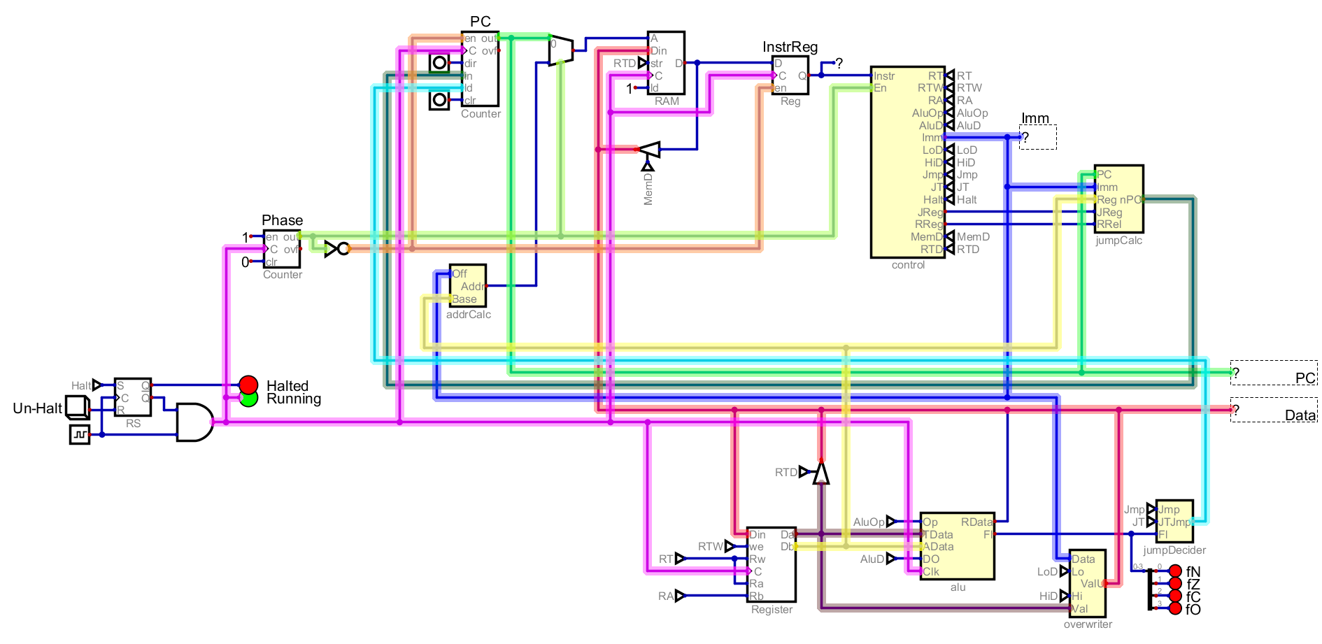
In particular, I notice that the jumpCalc and the jumpDecider only feed into the PC itself. I will reorganize them so that they are closer to the PC.

This does mean that the Flags are now on the bus, but I may want to use them for other things later so I think that is fine. You can see that the new PC (dark green) and the final decision to jump (cyan) are much shorter because they are near to the PC. Without highlight, you can see the current state of Atom below.
I think that this is better, but how much or even if it is better depends on the viewer. I have re-run all the test that I wrote at the begging on this circuit, and everything still works, so I feel safe with these updates.