Register Atom
Register Atom is a very simple version that will allow me to write data into registers and perform simple operations on them.
noop Instruction
I would like to define a noop instruction that, does nothing. Specifically,
because 0x0000 is the default state of RAM in Digital, I would like to have
0x0000 be my noop instruction so that by default nothing will happen.
Technically, everything is a noop to start as nothing will happen until I
implement some hardware, but defining this instruction will help me make some
initial decisions about op codes.
Generic Instruction Op Code
Specifically, noop will be part of the generic instruction set, and this means
that I need to reserve the op code 0b0000 for them.
Register Operations Op Code
I also want to have register operations, which I will assigned to op code
0b0001. Register operations all have a similar shape. I want to be able to
specify an operation to apply (separate from the op code) and specify two
registers to act on, the target and the argument. Since I need 4 bits in order
to address each of them, or 8 overall, and 4 bits are already dedicated to the
overall instruction op code I have 4 bits left over for the register op code. I
will use this form: 0001RRRRTTTTAAAA.
I will figure out what operations are supported over time, but for register Atom, I will start with a simple set of the following:
| Code | Operation | Description |
|---|---|---|
0000 | Add | Add the argument to the target |
0001 | Subtract | Subtract the argument from the target |
0010 | Move | Move the argument to the target |
Reflecting on these instructions, I just dedicated one sixteenth of my
instructions to register operations. When I use bits to describe an address or
data, you could think of each different address or piece of data being
referenced as a distinct instruction. Here, since I am using two register
addresses and four bits of data, I am actually defining 16 * 16 * 16 = 4096
instructions at once!
Setting Register Values
Performing register operations isn’t quite enough. All the registers start with
the value 0x0000, so you cannot usefully see the result of the operations I
have defined. I want to be able to set data directly into the registers using an
instruction.
Since each register is 16 bits, but I only have twelve bit available in an instruction after using four for the op code, I will need at least two instructions to set a full 16 bits of data. If I used twelve bits for the data, I would have no bits left over to select a register. This could be fine, I could always write to a certain register and move the result to a different register if needed.
However, since I need two instructions anyways, I could just write eight bits of
data with each instruction. This leaves me with 4 bits, which I can use to
specify a target register. One of the two instructions will write to the low
bits of the specified register, and the other to the high bits. For the low
bits, I will use op code 0b0010, and for the high bits I will use 0b0011.
This gives me two instructions that look like 0010TTTTDDDDDDDD and
0011TTTTDDDDDDDD.
Each of these op codes is fully used, so I have defined another two sixteenths of my instruction space with these simple instructions.
Implementation
You can see more of my exact thoughts about the implementation by reading through the commits between the tags #initial and #register-atom in the git repository.
Pieces
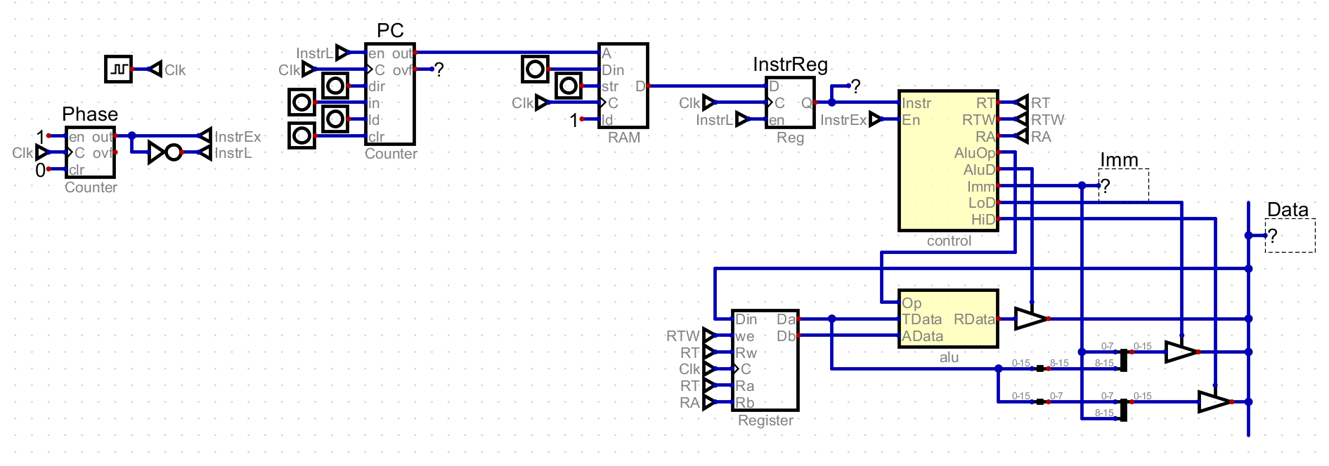
There are several core pieces of Atom that I had to create. The first is the clock and phase. The clock simply pulses on and off. Each of these signals causes the computer to move forward by one step. The phase module breaks these signals into two phases. During the first phase, the instruction to execute is loaded, and during the second it is executed.
The next is the PC, which is a register that stores the address in RAM of the next instruction to execute. This is not one of the general purpose registers, and so the register operations I defined cannot access it. The PC is incremented during the loading phase.
The address from the PC is fed into a RAM module. RAM currently just stores the instruction to execute, and the only address I need to use is the one from the PC. RAM does not depend on the clock signal yet, as only writing happens on the clock signal.
The output of RAM is saved in the instruction register, which holds the value during execution. This seems a little pointless now, and it is because the value coming from RAM will not change during execution. However it is preparing for the future where while an instruction is executed, the value coming out may be changed. This would be true while loading a value from RAM into a register.
The instruction from the instruction register is fed into the control module. The control module decodes an instruction into data and control signals. The data may be sent to other modules, and the control signals enable and control them. The control module also has an enable pin, and when it is low no data is written to any of the data outputs and no control signals are high. Ultimately, the control unit is the brain of the computer.
Atom has a 16 bit data bus that is used to transfer data between different modules. For register Atom, there are three sources that can put data on the bus. These are the ALU, as well as two special values that represent writing the high or low bits to the current target register. The only module that reads from the bus is the register file, which does so that that it can write one of the aforementioned values to a register.
The register file contains the 16 registers available on Atom. The register file takes two address, one for the target and one for the argument. The contents of the target and argument are always fed into the ALU, and will store the value on the data bus when the control module says so.
The ALU performs the register operations supported but Atom. It reads the target and argument values and writes it to the bus when the control modules says so.
The Control Module
The control module itself is the most complicated module in the computer. It is in charge of decoding an instruction into data and control signals. Data is multi bit information, like an immediate value or a register address. This data will be sent to other modules. It is essentially a shortcut to describe many instructions at once. Control signals are used to enable other modules based upon an instruction, or control when or where data is sent. Each instruction will have a unique output of control signals.
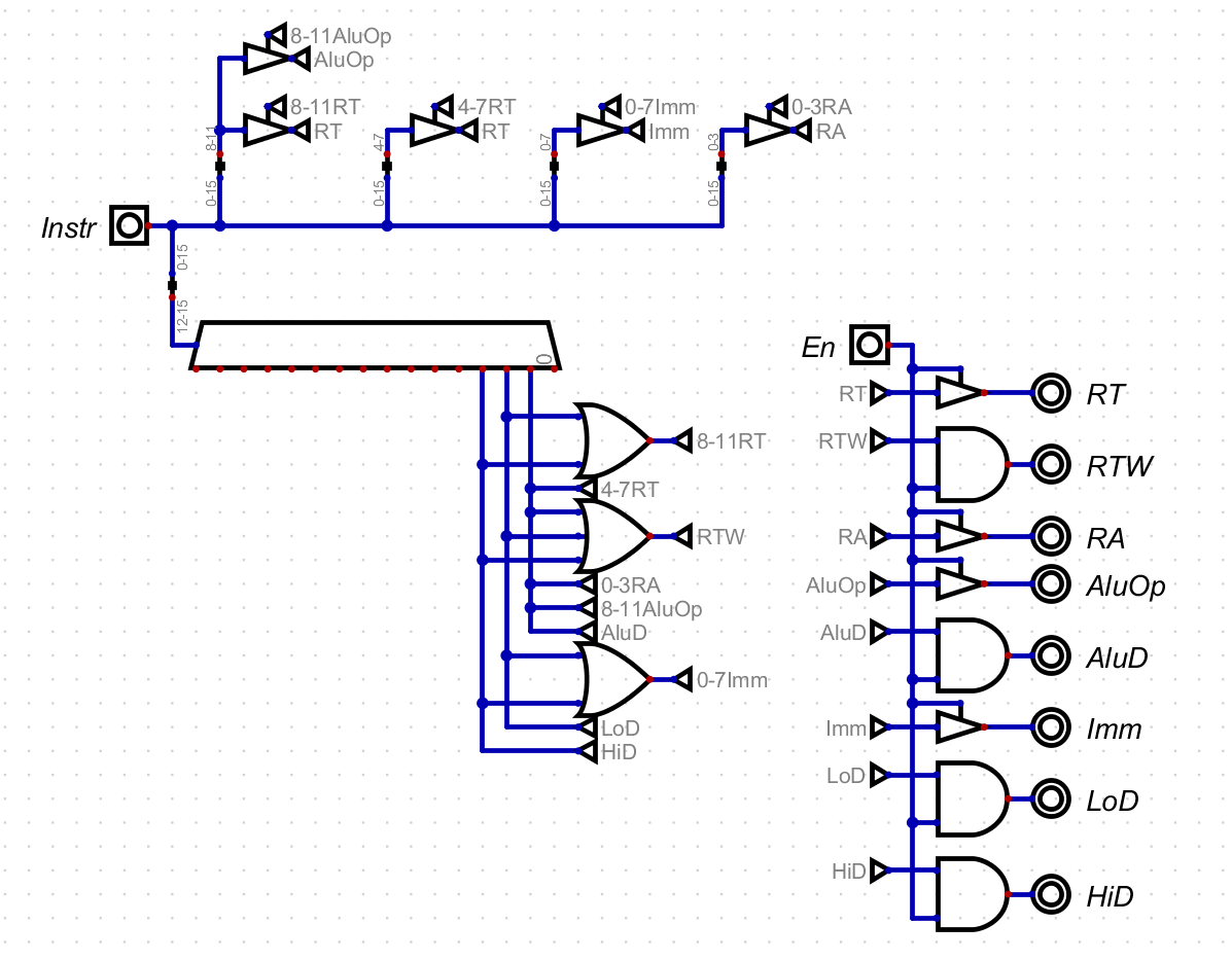
I won’t always describe the exact inner workings of the control module, but for this first implementation I want to describe my thoughts. First, I added an enable pin to the control module so that all signals can be controlled easily. When in the instruction loading phase, I don’t want garbage data or the last instruction to be controlling anything. I could add logic throughout the computer so that the clock signal only pulses when in the execution phase. However, I think it is cleaner to pull all of that into the control module.
The control module uses a decoder to decode the four op code bits. Each of the outputs represent one of the 16 op codes, and for each I can set relevant control signals and send sets of bits out as data.
A Small Program
With these instructions defined, I could create a simple program can perform any register operation on any value that I define with these two loading operations. For one, this will let me figure out how to setup a program in RAM. It also will prove that the instructions work.
In this program, I want to use every instruction I have defined. That means setting low and high bits as well as doing addition, subtraction, and a move. Here is a description of a simple program that does that.
Load 0x5 into the low bits of register 0
Load 0x3 into the low bits of register 1
Add the value of register 1 to register 0
Load 0x8 into the high bits of register 2
Subtract the value in register 0 from register 2
Move the value in register 2 to register 0
For each of these, I need to convert them into a hex instruction. Like the logic in the control module, I won’t always go into detail here. However, for this first small program I will go through every step.
The final converted program is as follows:
0x2005 0x2108 0x1001 0x3208 0x1120 0x1202To execute the program, you need to write them into Atom’s RAM module and turn
on the computer. In Digital, you can set the prog.bin file as program memory,
which will load it into RAM when stating the simulation. After running the
program, you will see the following values in the register file:
| Register | Value |
|---|---|
0x0 | 0x07F8 |
0x1 | 0x0003 |
0x2 | 0x07F8 |
These values prove that Atom worked! I can load data into the registers and perform simple operations on them. However, Atom still lacks the ability to make any kind of decisions based on the values of the registers, which I will tackle next.