I/O
The final type of operations I thought of in the beginning were I/O operations. I want to have the ability to communicate with device outside Atom, like a keyboard/terminal or a hard drive. These are the final pieces needed to enable me to start writing programs within atom: a way to interact with the computer while it is running, and a place to store data when it turns off. This page describes change between #atom-fibonacci and #atom-io in the git repository.
Design
The first thing I need to determine is what needs to be supported. I know that I want to be able to communicate with multiple devices. I probably always want access to a storage device, and almost always a keyboard and display (I know from previous work that these can be treated as a single device, more on that later). I want to be able to add more at the same time, so I am looking for at least three devices at the same time, and that probably means having four to make good use of the instruction bits.
I will call each device a peripheral. I need to be able to both read data from and send data to a peripheral, so I need a way to switch between these modes. I also need more than just the data itself. Imagine a storage device; I need to be able to write data to a specific location. Ultimately, this means that I need to be able to send two pieces of data. I will call them the data and address, and both of these will be 16 bits.
I also foresee the need to special state data about a device. I will call these flags, and right now a peripheral will just always emit them. This could be information about the ready state of the peripheral.
You could get really cleaver with this setup. Writing to a special address could change the behavior of a peripheral. You could swap to a different storage bank, which kind of resembles techniques I have heard about in old video game consoles.
Instructions
I will use the next available opcode, 0b1001, for peripheral instructions. I
need a single bit to toggle between reading and writing, and a single bit to
toggle reading data or flags. This leaves 10 bits that need to be spread between
the data and address registers, of which I only need 8 at most. That would leave
two bits for selecting the device, giving four devices. I will arrange theses
fields like this: 0b1001_DDFR_TTTT_AAAA.
- Bits 0 to 3 are the address register, selected due to existing circuitry that allows reading of a register value but not writing
- Bits 4 to 7 are the data register, which also has pre-existing circuitry that allows for writing as well
- Bit 8 switches between reading and writing, 0 to write and 1 to read
- Bit 9 switches between reading data and reading the flags
- Bits 10 to 11 select which device 0 to 3 to interact with
- Bits 12 to 15 are the opcode
Regex Assembly
These instructions are already pushing regex compilation to its limits. It is good when converting a hex character that results in 4 aligned bits, but it cannot really work with smaller or un-aligned data.
This set of instructions includes a 2 bit data field and two 1 bit flags, and it is the first set of instructions for which that is true. Because only three of the flag combinations are valid, you can think of there being 12 total different instructions (4 peripherals x 3 flag combinations) each of which take 2 aligned 4 bit values. This is just about bearable, but takes 12 regular expressions:
%s/^P0WRITE\s\+r\([0-9a-fA-F]\)\s\+r\([0-9a-fA-F]\).*$/90\2\1/e
%s/^P1WRITE\s\+r\([0-9a-fA-F]\)\s\+r\([0-9a-fA-F]\).*$/94\2\1/e
%s/^P2WRITE\s\+r\([0-9a-fA-F]\)\s\+r\([0-9a-fA-F]\).*$/98\2\1/e
%s/^P3WRITE\s\+r\([0-9a-fA-F]\)\s\+r\([0-9a-fA-F]\).*$/9C\2\1/e
%s/^P0READ\s\+r\([0-9a-fA-F]\)\s\+r\([0-9a-fA-F]\).*$/91\2\1/e
%s/^P1READ\s\+r\([0-9a-fA-F]\)\s\+r\([0-9a-fA-F]\).*$/95\2\1/e
%s/^P2READ\s\+r\([0-9a-fA-F]\)\s\+r\([0-9a-fA-F]\).*$/99\2\1/e
%s/^P3READ\s\+r\([0-9a-fA-F]\)\s\+r\([0-9a-fA-F]\).*$/9D\2\1/e
%s/^P0READF\s\+r\([0-9a-fA-F]\).*$/93\10/e
%s/^P1READF\s\+r\([0-9a-fA-F]\).*$/97\10/e
%s/^P2READF\s\+r\([0-9a-fA-F]\).*$/9B\10/e
%s/^P3READF\s\+r\([0-9a-fA-F]\).*$/9E\10/e
It is interesting how the assembly is already becoming an abstraction over the
instructions. The P*READF instructions don’t expose the address register even
though the instruction does require something to be specified. This is also true
of the various register operations, with different names greatly improving the
readability of a program.
Hardware
Since all peripherals work with the same inputs and outputs, the connection points can be standardized. This kind of ends up looking like a plug, which is how I imagine the peripherals are connected. In Digital, this means that as long as you create a sub-circuit with the right shape, you can drop it into a peripheral slot and communicate with it.
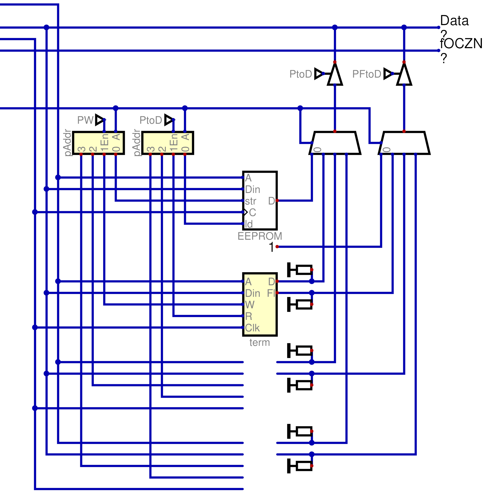
There were not any particular challenges with this implementation, mostly just routing data around. The 2 bit device selector is used to select which device is written to or read from, and data travels on the bus.
Storage
Storage is implemented with an EEPROM module in Digital. Digital will store the memory of this module to the .dig file, and so it persists between runs of Atom. However, for this to be true the EEPROM module has to be in the main circuit. To that end, I built the peripheral connection shape to match the shape of an EEPROM module.
Terminal
The terminal provides keyboard input and textual output from Atom. In Digital, the keyboard and terminal modules are separate. However, I treat the terminal as purely write-only and the keyboard as purely read-only, and so I can combine them into a single peripheral.
The keyboard makes use of flags, specifically a single bit that indicates if a character is available to be read.
Persistent Editor
With these two new peripherals, I can write a program that allows you to edit a string of test that is preserved between editing sessions.
Upon startup, the program read through storage (in this case, peripheral 0) looking for a null value that indicates the end of the text. For each character it does find, it emits it to the terminal and counts the length of the string.
After this setup is complete, it starts checking the flags coming back from the keyboard. Once it sees a character is ready to be consumed, it reads that character. If it is a backspace, it erases a character from the terminal and writes a null character to storage. If it is anything else, it is written both to the terminal and to storage.
Next Steps
From this point, I expect there to be a larger focus on software, but hardware additions nowhere near completed. I want to start working towards self hosted assembly within atom.
Notably, there is no way to tell what a device is at the moment. Your program would need to document what devices it expects in what peripheral slots. Again, this sounds somewhat familiar, and I think that there were computers that had this limitation. I am not yet doing any research, but this is definitely something I Want to look at when I do.